Capacitor Basics and Capacitance
A capacitor is a device that stores electrical energy by separating positive and negative charges on two conducting plates. Capacitance is the measure of a capacitor's ability to store charge per unit voltage.
What is a Capacitor?
Definition
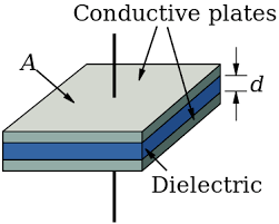
A capacitor consists of two conducting plates separated by an insulating material (dielectric) or vacuum/air. When a voltage is applied, equal and opposite charges accumulate on the plates, creating an electric field between them.
Capacitors are fundamental components in electrical circuits, used for energy storage, filtering, timing, and many other applications. The ability of a capacitor to store charge depends on its geometry and the material between the plates.
Capacitance Definition
Fundamental Formula
Capacitance is defined as the ratio of charge stored to the voltage applied:
$$C = \frac{Q}{V}$$
Where:
- C: Capacitance (Farads, F)
- Q: Charge stored on one plate (Coulombs, C)
- V: Voltage across the capacitor (Volts, V)
This relationship shows that:
- Higher capacitance means more charge stored for the same voltage
- Capacitance is constant for a given capacitor (independent of voltage)
- Units: 1 Farad = 1 Coulomb/Volt
- Practical values: Capacitors range from picofarads (pF) to farads (F)
Parallel Plate Capacitor
Parallel Plate Capacitance
For a parallel plate capacitor with area A and separation d:
$$C = \frac{\epsilon_0 A}{d}$$
Where:
- ε₀: Permittivity of free space = 8.85 × 10⁻¹² F/m
- A: Area of each plate (m²)
- d: Separation between plates (m)
This formula shows that capacitance depends on:
- Plate area: Larger area = higher capacitance
- Plate separation: Smaller separation = higher capacitance
- Dielectric material: Different materials affect capacitance (vacuum/air has κ = 1)
Properties of Capacitors
Fundamental Properties
- Charge storage: Stores equal and opposite charges on plates
- Energy storage: Stores electrical energy in the electric field
- Voltage relationship: Voltage is proportional to charge stored
- DC behavior: Acts as an open circuit in steady state
- AC behavior: Allows alternating current to pass
- Polarity: Some capacitors are polarized (electrolytic)
Charge and Voltage Relationship
Charge-Voltage Relationship
The charge stored on a capacitor is directly proportional to the voltage:
$$Q = CV$$
This means:
- Higher voltage = more charge stored
- Higher capacitance = more charge for same voltage
- Linear relationship between Q and V
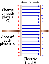
Electric Field Between Plates
Electric Field Formula
For a parallel plate capacitor, the electric field between plates is:
$$E = \frac{V}{d} = \frac{\sigma}{\epsilon_0}$$
Where σ is the surface charge density on the plates.
This shows that:
- Electric field is uniform between the plates
- Field strength depends on voltage and separation
- Field direction is from positive to negative plate
- Field lines are parallel and evenly spaced
Worked Examples
Example 1: Calculating Capacitance
Problem: A parallel plate capacitor has plates of area 0.01 m² separated by 1.0 mm. What is its capacitance?
Solution Steps:
- Given: A = 0.01 m², d = 1.0 × 10⁻³ m, ε₀ = 8.85 × 10⁻¹² F/m
- Formula: C = ε₀A/d
- Substitute: C = (8.85 × 10⁻¹²)(0.01)/(1.0 × 10⁻³)
- Calculate: C = 8.85 × 10⁻¹¹ F = 88.5 pF
Answer: The capacitance is 88.5 pF.
Example 2: Charge Storage
Problem: A 100 μF capacitor is charged to 12 V. How much charge is stored on each plate?
Solution Steps:
- Given: C = 100 × 10⁻⁶ F, V = 12 V
- Formula: Q = CV
- Substitute: Q = (100 × 10⁻⁶)(12)
- Calculate: Q = 1.2 × 10⁻³ C = 1.2 mC
Answer: Each plate stores 1.2 mC of charge (positive on one plate, negative on the other).
Example 3: Electric Field Between Plates
Problem: A capacitor has plates separated by 2.0 mm with a voltage of 50 V across them. What is the electric field between the plates?
Solution Steps:
- Given: V = 50 V, d = 2.0 × 10⁻³ m
- Formula: E = V/d
- Substitute: E = 50/(2.0 × 10⁻³)
- Calculate: E = 2.5 × 10⁴ N/C
Answer: The electric field between the plates is 2.5 × 10⁴ N/C, directed from the positive to negative plate.
Common Mistakes to Avoid
⚠️ Common Errors
- Confusing charge and voltage: Charge is proportional to voltage, not equal to it
- Forgetting units: Capacitance is in Farads, not Coulombs or Volts
- Ignoring polarity: Some capacitors are polarized and must be connected correctly
- Thinking capacitance changes with voltage: C is constant for a given capacitor
- Confusing with resistors: Capacitors behave very differently from resistors
Practice Problems
Practice Problem 1
Problem: A capacitor stores 5.0 μC of charge when connected to a 10 V battery. What is its capacitance?
Click for solution
Solution:
- Given: Q = 5.0 × 10⁻⁶ C, V = 10 V
- Formula: C = Q/V
- Substitute: C = (5.0 × 10⁻⁶)/10
- Calculate: C = 5.0 × 10⁻⁷ F = 0.5 μF
Answer: 0.5 μF
Practice Problem 2
Problem: A parallel plate capacitor has plates of area 0.05 m² separated by 0.5 mm. What is its capacitance?
Click for solution
Solution:
- Given: A = 0.05 m², d = 0.5 × 10⁻³ m, ε₀ = 8.85 × 10⁻¹² F/m
- Formula: C = ε₀A/d
- Substitute: C = (8.85 × 10⁻¹²)(0.05)/(0.5 × 10⁻³)
- Calculate: C = 8.85 × 10⁻¹⁰ F = 885 pF
Answer: 885 pF
Key Concepts Summary
- Capacitance is the ability to store charge per unit voltage
- Capacitance formula: C = Q/V for any capacitor
- Parallel plate formula: C = ε₀A/d
- Charge storage: Q = CV (linear relationship)
- Electric field: E = V/d between parallel plates
- Capacitance depends on: Geometry and dielectric material
Quick Reference
- Capacitance: \(C = \frac{Q}{V}\)
- Parallel plate: \(C = \frac{\epsilon_0 A}{d}\)
- Charge stored: \(Q = CV\)
- Electric field: \(E = \frac{V}{d}\)
- Units: Farads (F) = Coulombs/Volt
- Common prefixes: pF (10⁻¹²), nF (10⁻⁹), μF (10⁻⁶), mF (10⁻³)