Induced EMF and Voltage
Overview of Induced EMF
Induced electromotive force (emf) is the voltage generated in a conductor when the magnetic flux through it changes. This is the practical manifestation of Faraday's Law and is the basis for all electromagnetic induction phenomena. Understanding how to calculate and apply induced emf is crucial for analyzing electromagnetic devices and circuits.
The induced emf can be calculated using Faraday's Law and can be generated through various mechanisms including changing magnetic fields, moving conductors, and rotating loops. The magnitude and direction of the induced emf depend on the rate and nature of the flux change.
Calculating Induced EMF
Faraday's Law for Induced EMF
The induced emf is calculated using:
\[ \mathcal{E} = -\frac{d\Phi_B}{dt} \]
For a coil with N turns:
\[ \mathcal{E} = -N\frac{d\Phi_B}{dt} \]
Where:
- \(\mathcal{E}\) is the induced emf in volts (V)
- \(\Phi_B\) is the magnetic flux in webers (Wb)
- \(N\) is the number of turns in the coil
- \(\frac{d\Phi_B}{dt}\) is the rate of change of magnetic flux
Methods of Generating Induced EMF
Changing Magnetic Field
When a magnetic field changes in strength while the loop remains stationary:
\[ \mathcal{E} = -A\frac{dB}{dt} \]
This occurs in transformers and solenoids with time-varying currents.
- Field strength increases: positive emf
- Field strength decreases: negative emf
- Constant field: zero emf
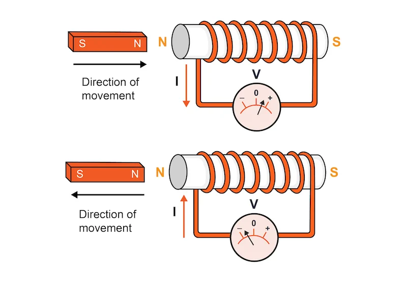
Moving Conductor
When a conductor moves through a magnetic field (motional emf):
\[ \mathcal{E} = BLv \]
Where L is the length of the conductor and v is its velocity perpendicular to the field.
- Used in generators
- Depends on velocity and field strength
- Direction given by right-hand rule
Magnetic Force on Moving Rods
When a rod enters a magnetic field, it experiences both induced emf and magnetic force:
\[ F = ILB \]
Where I is the induced current, L is the rod length, and B is the magnetic field strength.
- Force opposes the motion (Lenz's Law)
- Creates magnetic drag/resistance
- Used in eddy current brakes
- Requires work to overcome the force
Rotating Loop
When a loop rotates in a magnetic field:
\[ \mathcal{E} = BA\omega\sin(\omega t) \]
This produces alternating current (AC) and is the principle behind AC generators.
- Maximum emf when loop is perpendicular to field
- Zero emf when loop is parallel to field
- Frequency depends on rotation speed
Changing Area
When the area of a loop changes in a constant magnetic field:
\[ \mathcal{E} = -B\frac{dA}{dt} \]
This occurs in expanding or contracting loops and sliding conductors.
- Expanding area: negative emf
- Contracting area: positive emf
- Used in some types of sensors
Watch for better understanding
Interactive EMF Calculator
EMF Calculator
Calculate induced emf for different scenarios.
Result:
Enter parameters and click Calculate
Example Problems
Example 1: Changing Magnetic Field
Problem: A circular loop of radius 0.05 m is placed in a uniform magnetic field. The field increases from 0.2 T to 0.8 T in 0.5 seconds. What is the induced emf?
Solution:
- Calculate area: \(A = \pi r^2 = \pi(0.05)^2 = 0.00785 \text{ m}^2\)
- Calculate field change: \(\Delta B = 0.8 - 0.2 = 0.6 \text{ T}\)
- Calculate rate of change: \(\frac{dB}{dt} = \frac{0.6}{0.5} = 1.2 \text{ T/s}\)
- Calculate emf: \(\mathcal{E} = -A\frac{dB}{dt} = -(0.00785)(1.2) = -0.00942 \text{ V}\)
Answer: The induced emf is -9.42 mV.
Example 2: Moving Conductor
Problem: A metal rod of length 0.2 m moves at 5 m/s perpendicular to a 0.4 T magnetic field. What is the induced emf?
Solution:
- Use motional emf formula: \(\mathcal{E} = BLv\)
- Substitute values: \(\mathcal{E} = (0.4)(0.2)(5)\)
- Calculate: \(\mathcal{E} = 0.4 \text{ V}\)
Answer: The induced emf is 0.4 V.
Example 3: Rotating Loop
Problem: A rectangular loop of area 0.01 m² rotates at 120 rad/s in a 0.3 T magnetic field. What is the maximum induced emf?
Solution:
- Use rotating loop formula: \(\mathcal{E} = BA\omega\sin(\omega t)\)
- Maximum occurs when \(\sin(\omega t) = \pm 1\)
- Maximum emf: \(|\mathcal{E}| = BA\omega = (0.3)(0.01)(120)\)
- Calculate: \(|\mathcal{E}| = 0.36 \text{ V}\)
Answer: The maximum induced emf is 0.36 V.
Example 4: Magnetic Force on Moving Rod
Problem: A metal rod of length 0.2 m moves at 5 m/s perpendicular to a 0.4 T magnetic field. The rod has resistance 0.1 Ω. What is the magnetic force on the rod?
Solution:
- Calculate induced emf: \(\mathcal{E} = BLv = (0.4)(0.2)(5) = 0.4 \text{ V}\)
- Calculate induced current: \(I = \frac{\mathcal{E}}{R} = \frac{0.4}{0.1} = 4 \text{ A}\)
- Calculate magnetic force: \(F = ILB = (4)(0.2)(0.4) = 0.32 \text{ N}\)
- The force opposes the motion (Lenz's Law)
Answer: The magnetic force is 0.32 N, opposing the motion.
Formula Derivations (Not on AP Equation Sheet)
Derivation 1: Motional EMF Formula
Derive: \(\mathcal{E} = BLv\)
Method 1: Using Faraday's Law
- Consider a conductor moving through a magnetic field
- Flux change: \(\Delta\Phi_B = B \cdot \Delta A = B \cdot L \cdot \Delta x\)
- Rate of change: \(\frac{d\Phi_B}{dt} = B \cdot L \cdot \frac{dx}{dt} = BLv\)
- By Faraday's Law: \(\mathcal{E} = -\frac{d\Phi_B}{dt} = BLv\)
Method 2: Using Lorentz Force
- Electrons in the conductor experience Lorentz force: \(F = qvB\)
- This creates a separation of charge along the conductor
- The electric field created is: \(E = \frac{F}{q} = vB\)
- The potential difference is: \(\mathcal{E} = EL = vBL\)
Result: \(\mathcal{E} = BLv\) (NOT on equation sheet)
Derivation 2: Rotating Loop Maximum EMF
Derive: Maximum \(\mathcal{E} = BA\omega\)
Step-by-Step:
- Flux through rotating loop: \(\Phi_B = BA\cos(\omega t)\)
- Rate of change: \(\frac{d\Phi_B}{dt} = -BA\omega\sin(\omega t)\)
- By Faraday's Law: \(\mathcal{E} = -\frac{d\Phi_B}{dt} = BA\omega\sin(\omega t)\)
- Maximum occurs when \(\sin(\omega t) = \pm 1\)
- Maximum EMF: \(|\mathcal{E}_{max}| = BA\omega\)
Result: Maximum \(\mathcal{E} = BA\omega\) (NOT on equation sheet)
Derivation 3: Magnetic Force on Moving Rod
Derive: \(F = \frac{B^2L^2v}{R}\)
Step-by-Step:
- Motional EMF: \(\mathcal{E} = BLv\)
- Induced current: \(I = \frac{\mathcal{E}}{R} = \frac{BLv}{R}\)
- Magnetic force on current-carrying wire: \(F = ILB\)
- Substitute: \(F = \frac{BLv}{R} \cdot LB = \frac{B^2L^2v}{R}\)
- This force opposes the motion (Lenz's Law)
Result: \(F = \frac{B^2L^2v}{R}\) (NOT on equation sheet)
Applications of Induced EMF
- Electric Generators: Convert mechanical energy to electrical energy using rotating coils
- Transformers: Transfer electrical energy between circuits using changing magnetic fields
- Induction Motors: Use induced currents to create rotational motion
- Magnetic Sensors: Detect changes in magnetic fields for various applications
- Wireless Charging: Transfer energy without physical contact using induced emf
- Eddy Current Brakes: Use induced currents to create braking forces
Quick Quiz: Induced EMF
1. What is the unit of induced emf?
2. For a moving conductor, the induced emf is:
3. What happens to induced emf if the rate of flux change triples?
4. For a rotating loop, the maximum emf occurs when:
5. What type of current does a rotating loop in a magnetic field produce?
6. When a rod moves through a magnetic field, the magnetic force:
Learning Objectives
- Calculate Induced EMF: Use Faraday's Law to find induced emf in various situations
- Understand Different Mechanisms: Identify the different ways emf can be induced
- Apply Motional EMF: Calculate emf for moving conductors
- Analyze Rotating Loops: Understand AC generation in rotating loops
- Connect to Applications: Relate induced emf to real-world devices
Key Takeaways
- Rate Dependence: Induced emf depends on the rate of change of magnetic flux
- Multiple Mechanisms: EMF can be induced by changing fields, moving conductors, or rotating loops
- Direction: The negative sign indicates the direction of induced current
- Applications: Induced emf is the basis for generators, transformers, and many electrical devices
- Energy Conversion: Induced emf enables conversion between mechanical and electrical energy