LR Circuits
Overview: Inductor-Resistor Circuits
LR circuits consist of an inductor and resistor connected in series. When a voltage is applied, the current doesn't immediately reach its maximum value due to the inductor's opposition to changes in current. The current increases exponentially with a characteristic time constant.
These circuits are fundamental for understanding how inductors behave in DC circuits and are important for analyzing electromagnetic devices, filters, and power electronics.
Key Formulas
Time Constant
\[ \tau = \frac{L}{R} \]
Where:
- \(\tau\) is the time constant (s)
- \(L\) is the inductance (H)
- \(R\) is the resistance (Ω)
Note: This formula is NOT on the AP Physics C equation sheet.
Current as Function of Time
\[ I(t) = \frac{V}{R}(1 - e^{-t/\tau}) \]
Where:
- \(I(t)\) is the current at time \(t\) (A)
- \(V\) is the applied voltage (V)
- \(R\) is the resistance (Ω)
- \(\tau\) is the time constant (s)
Note: This formula is NOT on the AP Physics C equation sheet.
Key Concepts
Time Constant
The time constant determines how quickly the current changes:
- After \(\tau\): current reaches 63% of final value
- After \(2\tau\): current reaches 86% of final value
- After \(5\tau\): current reaches 99% of final value
- Larger \(L\) or smaller \(R\): slower current changes
Initial Behavior
When switch is first closed:
- Current starts at zero
- Inductor opposes current change
- Voltage across inductor equals applied voltage
- Voltage across resistor is zero
Final Behavior
After a long time:
- Current reaches maximum: \(I = \frac{V}{R}\)
- Inductor acts like a wire
- Voltage across inductor is zero
- Voltage across resistor equals applied voltage
Energy Storage
Energy is stored in the inductor's magnetic field:
- Energy: \(U = \frac{1}{2}LI^2\)
- Increases as current increases
- Maximum when current is maximum
Visualize an inductor at the start as a broken wire, current can't pass through. Once time progresses, current can pass through, acting like a wire.
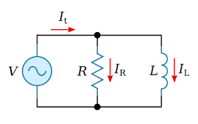
In this diagram, at the start all the current will flow through the resistor because the inductor acts like a broken wire. After a while, NO current passes through the resistor because it gets short circuted - the inductor is the path of least resistance so all the current passes through there.
Derivations (Not on AP Equation Sheet)
Derivation: Current Formula
Step-by-Step:
- Kirchhoff's voltage law: \(V = IR + L\frac{dI}{dt}\)
- Rearrange: \(\frac{dI}{dt} = \frac{V - IR}{L}\)
- This is a first-order differential equation
- Solution: \(I(t) = \frac{V}{R}(1 - e^{-t/\tau})\) where \(\tau = \frac{L}{R}\)
Example Problems
Example 1: Time Constant
Problem: An LR circuit has \(L = 0.5\) H and \(R = 2\) Ω. What is the time constant?
- \(\tau = \frac{L}{R} = \frac{0.5}{2} = 0.25\) s
Answer: 0.25 s
Example 2: Current Calculation
Problem: In the above circuit with \(V = 10\) V, what is the current after 0.5 s?
- \(I(t) = \frac{V}{R}(1 - e^{-t/\tau}) = \frac{10}{2}(1 - e^{-0.5/0.25})\)
- \(I(0.5) = 5(1 - e^{-2}) = 5(1 - 0.135) = 4.33\) A
Answer: 4.33 A
Example 3: Energy Storage
Problem: What is the energy stored in the inductor when current is maximum?
- Maximum current: \(I = \frac{V}{R} = \frac{10}{2} = 5\) A
- Energy: \(U = \frac{1}{2}LI^2 = \frac{1}{2}(0.5)(5)^2 = 6.25\) J
Answer: 6.25 J
Quiz: LR Circuits
1. What is the time constant for \(L = 2\) H and \(R = 4\) Ω?
2. After one time constant, the current reaches:
3. When the switch is first closed, the voltage across the inductor is:
4. After a long time, the inductor acts like:
Learning Objectives
- Calculate time constant for LR circuits
- Determine current as function of time
- Understand initial and final behavior
- Calculate energy stored in inductor
Key Takeaways
- Current increases exponentially with time constant \(\tau = \frac{L}{R}\)
- After \(\tau\) seconds, current reaches 63% of final value
- Inductor opposes current changes initially
- Energy is stored in the magnetic field
LR Circuit Interactive Simulation
Explore how current changes over time in an LR circuit: