Magnetic Force on Current-Carrying Wires
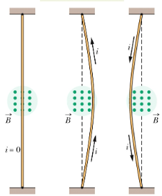
Current-carrying wires experience magnetic forces when placed in magnetic fields. This fundamental interaction is the basis for electric motors, galvanometers, and many other electromagnetic devices. Understanding these forces is crucial for analyzing electromagnetic systems.
The Magnetic Force on a Wire
⚡ Magnetic Force Formula
The magnetic force on a current-carrying wire is given by:
This force is perpendicular to both the current direction and the magnetic field.
Variables in the Formula
- I: Current in the wire (A)
- L: Length of wire in the magnetic field (m)
- B: Magnetic field strength (T)
- θ: Angle between current direction and magnetic field direction
Key Characteristics
- Magnitude: \(F_B = ILB\sin\theta\) where θ is the angle between current and field
- Direction: Perpendicular to both current and magnetic field (palm rule)
- Right-Hand Rule: Point fingers in field direction, thumb in current direction, palm faces force direction
- Dependence: Force depends on current, wire length, and field strength
- Vector Nature: Force is a vector quantity with magnitude and direction
Example: Basic Wire Force Calculation
Problem: A 0.5 m wire carries 3 A of current perpendicular to a 0.2 T magnetic field. Calculate the magnetic force on the wire.
Step 1: Identify Given Values
- Current: I = 3 A
- Length: L = 0.5 m
- Magnetic field: B = 0.2 T
- Angle: θ = 90° (perpendicular)
Step 2: Apply Force Formula
- \(F_B = ILB\sin\theta\)
- \(F_B = (3)(0.5)(0.2)\sin(90°)\)
- \(F_B = 0.3\) N
Step 3: Determine Direction
- Use right-hand rule: point fingers in magnetic field direction
- Point thumb in current direction
- Palm faces in force direction
Answer
The magnetic force is 0.3 N, directed perpendicular to both the current and magnetic field.
Why Magnetic Forces Arise from Current-Carrying Wires
🔍 Understanding the Source of Magnetic Forces
Magnetic forces on current-carrying wires arise from the collective motion of charged particles.
Each moving electron in the wire experiences a magnetic force, and these individual forces combine to create the net force on the wire.
Microscopic Explanation
- Moving Electrons: Each electron in the wire moves with drift velocity
- Individual Forces: Each electron experiences Lorentz force: \(\vec{F} = q\vec{v} \times \vec{B}\)
- Collective Effect: All electron forces add up to create net force on wire
- Wire Structure: Positive ions in wire lattice provide equal and opposite forces
Example: Force on Individual Electrons
Problem: Explain how the magnetic force on a wire relates to forces on individual electrons.
Step 1: Electron Motion
- Electrons move with drift velocity through wire
- Each electron has charge q = -1.6 × 10⁻¹⁹ C
- Electrons move in direction opposite to conventional current
Step 2: Individual Forces
- Each electron experiences: \(\vec{F} = q\vec{v}_d \times \vec{B}\)
- Force direction depends on electron velocity and field
- All electrons experience force in same direction
Step 3: Net Force
- Total force = Sum of all individual electron forces
- Net force = Number of electrons × Force per electron
- This gives the macroscopic force formula: \(\vec{F}_B = I\vec{L} \times \vec{B}\)
Answer
The magnetic force on a wire is the sum of individual Lorentz forces on all moving electrons in the wire, resulting in the macroscopic force formula.
Electric Motor Principles
⚙️ Electric Motor Operation
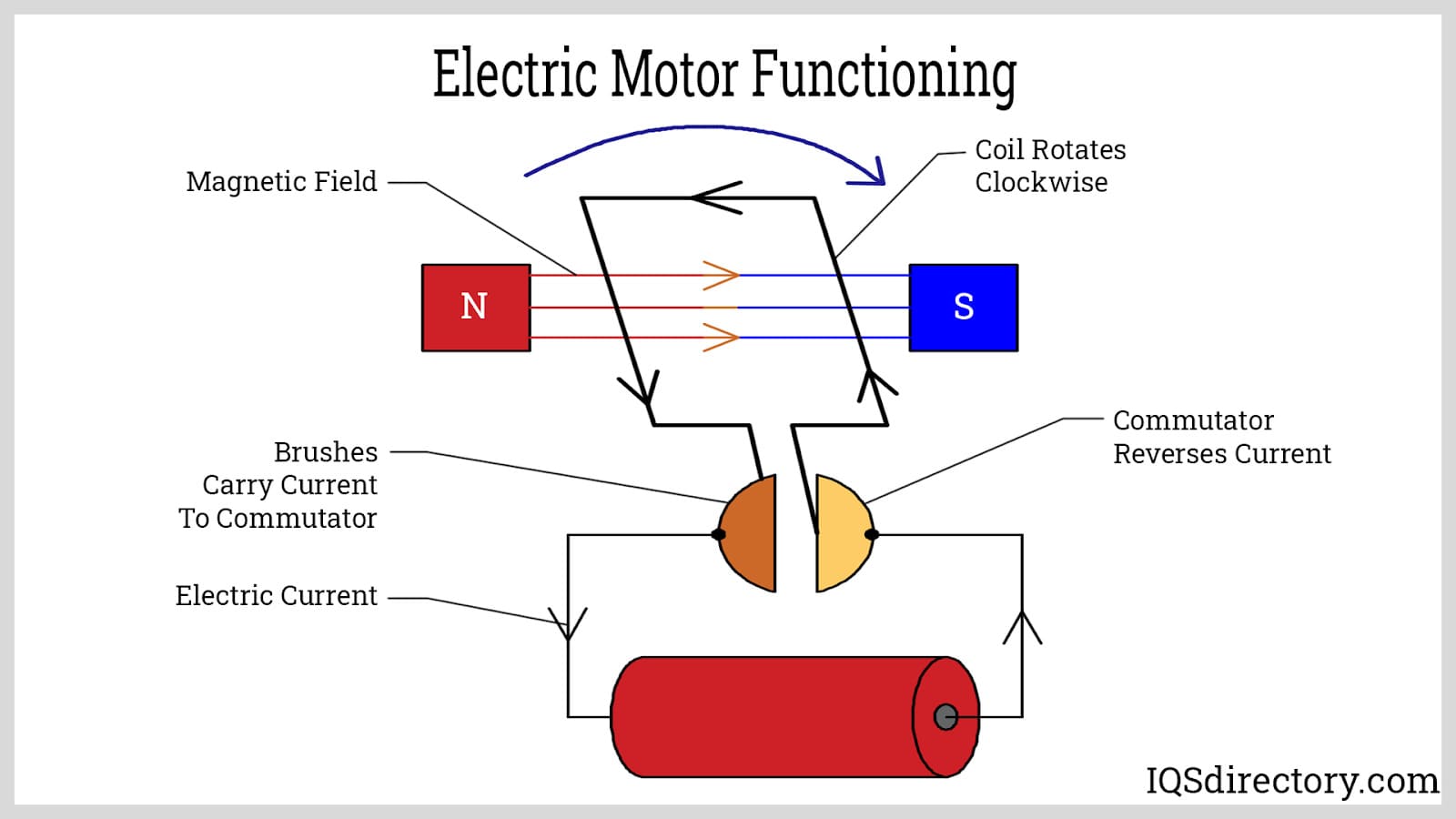
Electric motors convert electrical energy to mechanical energy using magnetic forces on current-carrying wires.
The basic motor consists of a current-carrying coil in a magnetic field that experiences forces.
Motor Components
- Armature: Current-carrying coil that experiences magnetic forces
- Magnetic Field: Usually provided by permanent magnets or electromagnets
- Commutator: Reverses current direction to maintain rotation
- Brushes: Electrical contacts that connect to power source
Example: Motor Force Calculation
Problem: A motor has 100 turns of wire, each with length 0.1 m, carrying 1 A in a 0.3 T field. Calculate the total magnetic force on the coil.
Step 1: Calculate Total Wire Length
- Single turn length: L₁ = 0.1 m
- Total length: (L_total) = N × L₁ = (100)(0.1) = 10 m
Step 2: Calculate Magnetic Force
- \(F_B = ILB\sin\theta\)
- \(F_B = (1)(10)(0.3)\sin(90°)\)
- \(F_B = 3\) N
Step 3: Motor Operation
- Force causes coil to move
- Commutator reverses current to maintain motion
- Converts electrical energy to mechanical motion
Answer
The motor experiences a total magnetic force of 3 N on the coil, causing rotation and converting electrical to mechanical energy.
Force Between Parallel Wires
Mutual Magnetic Forces
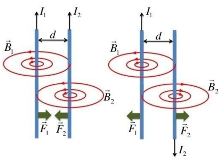
- Parallel Currents: Wires attract each other
- Antiparallel Currents: Wires repel each other
- Force per Unit Length: \(\frac{F}{L} = \frac{\mu_0 I_1 I_2}{2\pi d}\)
- Distance Dependence: Force decreases with wire separation
Derivation of the Force Between Parallel Wires
🔬 Step-by-Step Derivation (come back after learning Ampere's law)
We derive the force between two parallel wires by combining Ampere's law and the magnetic force formula.
This derivation shows how the magnetic field from one wire creates a force on the other wire.
Magnetic Field from Wire 1
Using Ampere's law, the magnetic field at a distance d from a long straight wire carrying current I₁ is:
Force on Wire 2
Wire 2, carrying current I₂, experiences a magnetic force due to the field B₁ from wire 1:
Since the current in wire 2s perpendicular to the magnetic field from wire 1, θ = 90° and sin(90 = 1:
Step 3: Substitute the Magnetic Field
Substituting the expression for B₁ from Step 1:
Step 4: Divide per Unit Length
Dividing both sides by L to get the force per unit length:
Step 5: Direction of Force
- Parallel Currents (same direction): Wires attract each other
- Antiparallel Currents (opposite directions): Wires repel each other
- Right-Hand Rule: Use to determine force direction
Example: Force Between Wires
Problem: Two parallel wires carry 5 A and 3 A in the same direction, separated by 0.1 m. Calculate the force per unit length.
Step 1: Identify Given Values
- Current 1: I₁ = 5 A
- Current 2: I₂ = 3 A
- Separation: d = 0.1 m
- Same direction: attractive force
Step 2: Apply Force Formula
- \(\frac{F}{L} = \frac{\mu_0 I_1 I_2}{2\pi d}\)
- \(\frac{F}{L} = \frac{(4\pi \times 10^{-7})(5)(3)}{2\pi(0.1)}\)
- \(\frac{F}{L} = 3 \times 10^{-5}\) N/m
Step 3: Determine Direction
- Same current direction: attractive force
- Wires are pulled toward each other
Answer
The force per unit length is 3 × 10⁻⁵ N/m, attracting the wires toward each other.
Practical Applications
🔧 Real-World Applications
Magnetic forces on current-carrying wires have numerous practical applications in modern technology.
These applications range from electric motors to precision measurement devices.
Key Applications
- Electric Motors: Convert electrical energy to mechanical motion
- Galvanometers: Measure small currents and voltages
- Loudspeakers: Convert electrical signals to sound
- Magnetic Levitation: Maglev trains use magnetic forces for propulsion
- Circuit Breakers: Use magnetic forces to trip when current is too high
- Electric Meters: Measure power consumption in homes
Example: Loudspeaker Operation
Problem: Explain how a loudspeaker uses magnetic forces on current-carrying wires.
Step 1: Voice Coil
- Coil of wire attached to speaker cone
- Carries audio signal current
- Located in permanent magnetic field
Step 2: Magnetic Force
- Current creates magnetic force on coil
- Force direction depends on current direction
- Force magnitude depends on current magnitude
Step 3: Sound Production
- Coil moves back and forth with audio signal
- Speaker cone moves with coil
- Creates sound waves in air
Answer
The loudspeaker uses magnetic forces on the voice coil to convert electrical audio signals into mechanical motion, producing sound waves.
⚠️ Common Misconceptions
- Force direction: Always perpendicular to both current and field, not parallel
- Torque direction: Tends to align magnetic moment with field direction
- Wire length: Only the component of length perpendicular to field matters
- Current direction: Conventional current direction, not electron flow
- Field strength: Force is proportional to field strength, not field direction
Key Takeaways
- Force Formula: \(\vec{F}_B = I\vec{L} \times \vec{B}\) for magnetic force on wires
- Electron Motion: Forces arise from individual Lorentz forces on moving electrons
- Electric Motors: Convert electrical to mechanical energy using magnetic forces
- Galvanometers: Measure currents using balance of magnetic and restoring forces
- Parallel Wires: Attract when currents are parallel, repel when antiparallel
- Palm Rule: Point fingers in field direction, thumb in current direction, palm faces force direction
- Applications: Used in motors, speakers, meters, and many other devices
- Energy Conversion: Magnetic forces enable electrical-to-mechanical energy conversion