Single-Loop Circuit Analysis
Single-loop circuit analysis is the foundation of circuit theory. These circuits contain one complete path for current flow and can be analyzed using Kirchhoff's Voltage Law (KVL). Understanding single-loop analysis is essential for more complex multi-loop circuits.
What is a Single-Loop Circuit?
Characteristics of single-loop circuits:
- One Current: Same current flows through all components
- Series Connection: All components are in series
- KVL Analysis: One KVL equation is sufficient
- Simple Solution: Direct application of Ohm's Law
Systematic Analysis Method
For single-loop circuits:
$$\sum V_{sources} - \sum IR = 0$$Worked Example: Basic Single-Loop Circuit
Example: Find current and voltage drops
Problem: A 24V battery is connected to three resistors in series: R₁=4Ω, R₂=6Ω, R₃=2Ω. Find the current and voltage drop across each resistor.
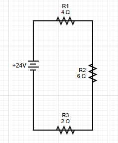
Step 1: Identify the Circuit
This is a single-loop circuit with one battery and three resistors in series.
Step 2: Choose Loop Direction
Let's traverse the loop clockwise, starting from the battery.
Step 3: Write KVL Equation
Step 4: Solve for Current
Step 5: Find Voltage Drops
Step 6: Verify Results
Results Summary
| Component | Resistance (Ω) | Current (A) | Voltage Drop (V) | Power (W) |
|---|---|---|---|---|
| R₁ | 4 | 2 | 8 | 16 |
| R₂ | 6 | 2 | 12 | 24 |
| R₃ | 2 | 2 | 4 | 8 |
| Total | 12 | 2 | 24 | 48 |
Answer
The current is 2A, and the voltage drops are 8V, 12V, and 4V respectively.
Complex Single-Loop Examples
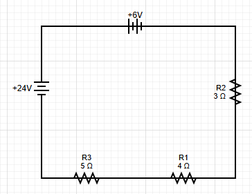
Example: Multiple Voltage Sources
Problem: A circuit has two batteries (18V and 6V) and three resistors (3Ω, 4Ω, 5Ω) in series. Find the current and voltage drops.
Step 1: Write KVL Equation
Remember: going from the positive to the negative terminal of the battery is a voltage drop.
Step 2: Solve for Current
Step 3: Find Voltage Drops
Answer
The current is 1A, and the voltage drops are 3V, 4V, and 5V respectively.
Common Single-Loop Configurations
🔋 Single Battery with Multiple Resistors
Application: Most common single-loop configuration
⚡ Multiple Batteries in Series
Application: Battery packs and voltage addition
🔄 Opposing Batteries
Application: When batteries oppose each other
Power Analysis in Single-Loop Circuits
Power Calculations
In single-loop circuits, power can be calculated for each component:
Power Formulas
- Resistor Power: P = I²R = V²/R = IV
- Battery Power: P = IV (positive if supplying, negative if receiving)
- Total Power: P_total = I²R_total
Example: Power Calculation
Using the previous example with I = 2A:
Key Takeaways Summary
🎯 Essential Single-Loop Concepts
- One Current: Same current flows through all components
- Series Connection: All components are in series
- KVL Analysis: One equation is sufficient
- Simple Solution: Direct application of Ohm's Law
⚡ Analysis Steps
- Identify: Confirm single-loop configuration
- Choose Direction: Pick clockwise or counterclockwise
- Write KVL: Sum all voltages = 0
- Solve Current: I = ΣV_sources / ΣR
- Find Voltages: V_i = I × R_i
🔍 Key Formulas
- Current: I = V_total / R_total
- Voltage Drop: V_i = I × R_i
- Power: P_i = I²R_i = V_i²/R_i
- Verification: ΣV_drops = ΣV_sources
✅ Verification Methods
- Voltage Check: Sum of voltage drops = battery voltage
- Current Check: Same current through all components
- Power Check: Power supplied = Power dissipated
- Ohm's Law: V = IR must hold for each resistor
💡 Pro Tips for Single-Loop Analysis
- Start Simple: Begin with basic single-battery circuits
- Be Systematic: Follow the 5-step method consistently
- Check Signs: Verify sign conventions for voltage sources
- Verify Results: Always check that your answer makes sense
- Practice Regularly: Single-loop analysis is the foundation for complex circuits